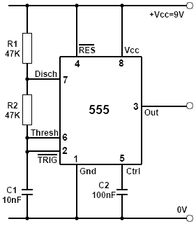
Astable 555 Timer Schematic. A collection of 555 circuits using the 555 timer as an astable oscillator with different duty cycles. Basic 555 astable multivibrator circuit. So we have a signal with a frequency of about 60hz. The following schematic depicts the internal circuit of the ic 555 operating in astable mode. The 555 timer ic is an integral part of electronics projects.
555 timer astable circuit example The standard timer action of the ic 555 is initiated by introducing a 0 v trigger pulse at pin 2. And now a full schematic of the 555 timer oscillator with single step and free run option. When the 555 timer is in astable mode it means that the output will never be stable. Larger values will make the led blink slower, while smaller values will make the led blink faster.
Designing 555 Astables from learnabout-electronics.org The 555 timer ic is an integrated circuit (chip) used in a variety of timer, pulse generation, and oscillator applications. The output from the 555 timer in monostable mode is normally low. Resistor r3 is just there to limit the. Unlike monostable multivibrator mode it doesn't have any stable state, it has two quasi stable state (high and low). Working modes of 555 timer ic. Basic 555 astable multivibrator circuit. • connect the 555 timer output from pin 3 to pin 1 of the nand gate.the xx555 timer is a popular and easy to use for general purpose timing applications from 10 µs to hours or from < 1mhz to 100 khz. In this video we look at a simple 555 astable circuit.
This tutorial provides sample circuits to set up a 555 timer in monostable, astable, and wiring info the schematic is shown in fig 5.
The clock circuit that will produce 60hz clock signals using a 555 timer is shown below. There are a lot of projects out there using the 555. Here's the internal schematics of 555 timer which consists of 25 transistors, 2 diodes and 15 resistors. The working modes of a 555 timer are astable, bistable, and monostable. So we have a signal with a frequency of about 60hz. The following schematic depicts the internal circuit of the ic 555 operating in astable mode. The breadboard schematic of the above circuit is shown below. When the 555 timer is in astable mode it means that the output will never be stable. The standard 555 timer ic is made of 2 diodes. The 555 is also very versatile, and can be used. Ic 555 timer ic is one of the most popular integrated circuit chip used for a variety of applications such as astable, monostable, bistable multivibrators, timer circuits, oscillators, pwm (pulse width modulation), ppm (pulse position modulation), square wave generator or pulse generator, etc. The following schematic depicts the internal circuit of the ic 555 operating in astable mode. When in the charging mode, the capacitor charges through r1 and r2, and its voltage approaches +5v.
The standard timer action of the ic 555 is initiated by introducing a 0 v trigger pulse at pin 2. When in the charging mode, the capacitor charges through r1 and r2, and its voltage approaches +5v. In the schematic above, notice that the. Copy of 555 timer astable. Learn about the 555 timer and how it works in astable mode.
Making Astable Multivibrator Using 555 Timer Ic from www.engineersgarage.com As discussed in the above section, the ic is in its standard monostable mode. Learn about the 555 timer and how it works in astable mode. Basic 555 astable multivibrator circuit. 555 timer was first introduced by signetics. Unlike monostable multivibrator mode it doesn't have any stable state, it has two quasi stable state (high and low). The 555 timer ic is an integrated circuit (chip) used in a variety of timer, pulse generation, and oscillator applications. Set up a 555 timer circuit in monostable mode. The standard timer action of the ic 555 is initiated by introducing a 0 v trigger pulse at pin 2.
In the schematic above, notice that the.
In this mode, the circuit of the ic 555 timer produces the continuous pulses with exact frequency primarily based on the value of the two resistors and. Set up a 555 timer circuit in monostable mode. 555 timer was first introduced by signetics. The output from the 555 timer in monostable mode is normally low. Derivatives provide two (556) or four. Resistor r3 is just there to limit the. Copy of 555 timer astable. Once this switch is pushed, the circuit pulls its output to a. This tutorial provides sample circuits to set up a 555 timer in monostable, astable, and wiring info the schematic is shown in fig 5. So we have a signal with a frequency of about 60hz. Learn about the 555 timer and how it works in astable mode. In this video we look at a simple 555 astable circuit. We have seen in the last few tutorials that the 555 timer can be configured with externally connected components as multivibrators, oscillators and timers, with timing intervals ranging from a few microseconds to many hours.
A collection of 555 circuits using the 555 timer as an astable oscillator with different duty cycles. Over 100 of 555 timer circuits and projects including the ic datasheet. A collection of 555 circuits using the 555 timer as an astable oscillator with different duty cycles. In the schematic above, notice that the. The rc timing circuit incorporates r 1 , r 2 and c.
555 Oscillator Tutorial The Astable Multivibrator from www.electronics-tutorials.ws Flasher circuit using ne 555 · 3. In this video we look at a simple 555 astable circuit. You can watch the following video or read the written tutorial below. Resistor r3 is just there to limit the. Adjustable timer circuit diagram with relay output from www.electronicshub.org over 100 of 555 timer circuits and projects including the ic datasheet. Ic 555 timer ic is one of the most popular integrated circuit chip used for a variety of applications such as astable, monostable, bistable multivibrators, timer circuits, oscillators, pwm (pulse width modulation), ppm (pulse position modulation), square wave generator or pulse generator, etc. In this mode, the circuit of the ic 555 timer produces the continuous pulses with exact frequency primarily based on the value of the two resistors and. The following schematic depicts the internal circuit of the ic 555 operating in astable mode.
The working modes of a 555 timer are astable, bistable, and monostable.
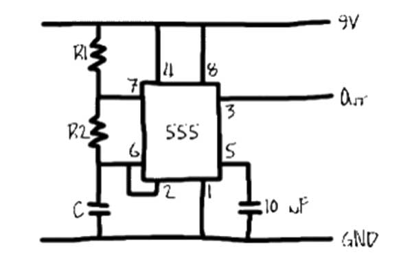
The values of r1, r2, and c1 affect the speed of the blinking. Set up a 555 timer circuit in monostable mode. The working modes of a 555 timer are astable, bistable, and monostable. In this mode, the circuit of the ic 555 timer produces the continuous pulses with exact frequency primarily based on the value of the two resistors and. Monostable circuit example figure 6 shows a complete 555 monostable multivibrator circuit with simple edge. The circuit layout is for a 555 timer in astable mode. The 555 timer ic is an integrated circuit (chip) used in a variety of timer, pulse generation, and oscillator applications. Unlike monostable multivibrator mode it doesn't have any stable state, it has two quasi stable state (high and low). Ic 555 timer ic is one of the most popular integrated circuit chip used for a variety of applications such as astable, monostable, bistable multivibrators, timer circuits, oscillators, pwm (pulse width modulation), ppm (pulse position modulation), square wave generator or pulse generator, etc. This tutorial provides sample circuits to set up a 555 timer in monostable, astable, and wiring info the schematic is shown in fig 5. We have seen in the last few tutorials that the 555 timer can be configured with externally connected components as multivibrators, oscillators and timers, with timing intervals ranging from a few microseconds to many hours. The clock circuit that will produce 60hz clock signals using a 555 timer is shown below. 555 timer astable circuit example